How C4 Model + DDD Fixed My Team's Architecture Diagrams
How C4 model and DDD fixed our architecture diagrams: shared vocabulary, diagrams as code, and the C3 trap. Practical workflow for agile teams.
How C4 Model + DDD Fixed My Team’s Architecture Diagrams
10 min read
There’s a draw.io file in almost every project I’ve ever joined. It lives in a Confluence page nobody visits, last updated sometime the previous year. It has boxes in three different colors, arrows pointing in six directions, and labels like “Service Layer” and “Data Thing.”
Nobody knows what the dashed line means. The person who drew it left six months ago.
We’ve all been there. Most teams respond by drawing a new diagram, putting it somewhere slightly different, and repeating the cycle. The documentation problem isn’t a discipline problem; it’s a system problem.
I spent years trying different tools and approaches before landing on a combination that actually sticks: the C4 model for structure, Domain-Driven Design for vocabulary, and diagrams-as-code for the workflow. This isn’t a silver bullet, but it’s the closest I’ve found to architecture documentation that survives contact with a real team.
The Goldilocks Problem
Before getting into what C4 is, it’s worth naming the two failure modes it sits between.
Failure Mode 1: The Random Shapes Diagram
Ad-hoc diagrams (draw.io, Visio, Miro whiteboards, PowerPoint slides) are fast to create and nearly impossible to read if you weren’t the one who made them. There’s no convention for what a box means versus a cylinder versus a cloud shape. Arrows can mean “calls,” “depends on,” “sends data to,” or “vaguely related to.” One person’s dashed line is another person’s async boundary.
Simon Brown, who created the C4 model, describes these as producing “inconsistent notation, ambiguous naming, unlabelled relationships, mixed abstractions.” The author of the diagram understands it perfectly. Everyone else is guessing.
Failure Mode 2: The UML That Nobody Maintains
The standard response to ad-hoc diagrams is to reach for a formal standard. UML has been around since the 1990s, it’s thorough, and it has solid tooling. For certain contexts (regulated industries, formal specifications, safety-critical systems) it’s the right call.
But for most agile teams, UML carries too much ceremony. As Ben Morris wrote: “Nobody really understands it beyond development teams of a certain vintage. It’s a weighty and detailed methodology that doesn’t fit so well with agile.” Sequence diagrams, class diagrams, component diagrams: the notation requires training to read and discipline to maintain. In a fast-moving codebase, diagrams fall behind the code within weeks. That’s documentation rot: the diagram exists, it just describes a system that no longer does.
The middle ground
C4 sits between these two failure modes: just enough structure for shared understanding, light enough to actually get maintained.
It’s not a formal modeling language; it has no strict syntax, it’s tooling-independent, and it doesn’t require certification to read. But it’s not “anything goes” either. It gives you four fixed levels of abstraction, standardized element types, and a clear purpose for each level. Any engineer who reads a C4 diagram for the first time can orient themselves in minutes.
What C4 Actually Is
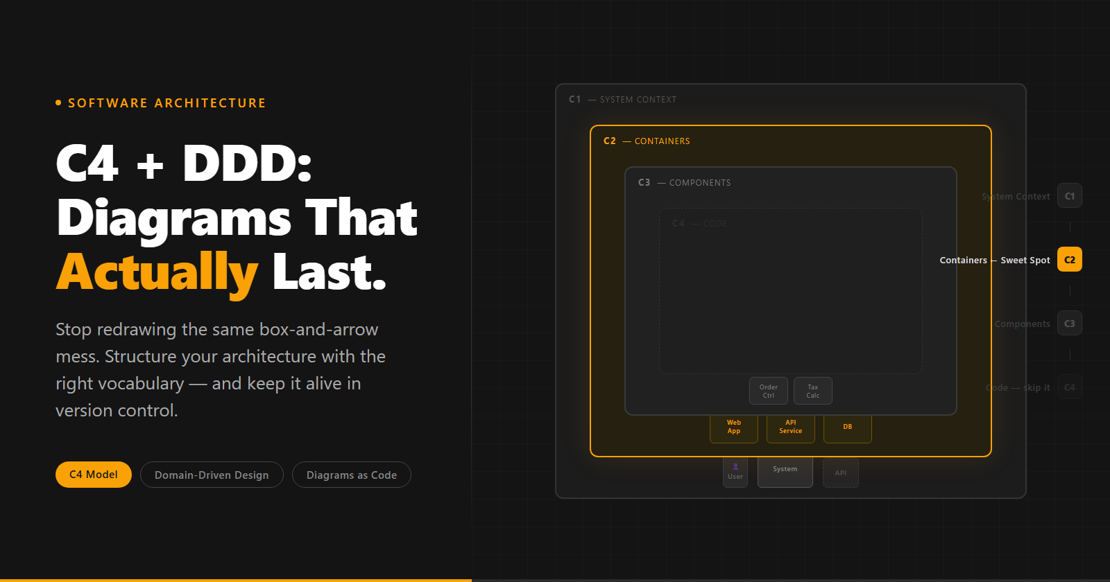
C4 stands for Context, Container, Component, Code. Each level zooms into the previous one, and each level has a defined audience.
C1: System Context The highest level. Shows your system as a single box surrounded by the actors who interact with it: the people who use it and the external systems it connects to. A C1 diagram should fit on a single slide and be readable by anyone in the room, including non-technical stakeholders.
C2: Container Zooms into your system. A “container” in C4 isn’t Docker; it’s any separately deployable unit: a web app, an API, a database, a message queue, a serverless function. C2 shows the high-level tech stack and how the containers communicate. This is the level where most teams get 90% of their value.
C3: Component Zooms into a single container to show its internal structure: logical modules, services, controllers. This is where maintenance cost starts climbing. More on that in a moment.
C4: Code Zooms into a single component to show implementation details: classes, interfaces, methods. Simon Brown himself says this level is rarely worth drawing by hand. In practice, it gets auto-generated from code or skipped entirely. If you’re hand-drawing C4 code diagrams in a moving codebase, stop; they’ll be stale before the PR is merged.
The mental model that clicked for me: C4 is Google Maps. C1 is the satellite view of the city. C2 is the neighbourhood. C3 is the street. C4 is the floor plan of a single building. You don’t open the floor plan when you’re trying to figure out which highway to take. The full notation and examples are on the official C4 site.
DDD First, Then C4
I came to C4 through DDD, not the other way around.
Domain-Driven Design gave my team the vocabulary first. We ran event-storming sessions, identified our Bounded Contexts, and mapped out where the same word meant different things in different parts of the business. “Order” in the Sales context meant a customer’s intent to purchase. “Order” in Fulfillment meant a physical instruction to move inventory. Same word, completely different concept, different teams, different data models.
Once we had that vocabulary, something clicked when I looked at a C2 diagram: the Bounded Contexts we’d identified in our DDD sessions mapped almost exactly to C2 Containers. The Sales Order Context became the “Order API” container. The Fulfillment Context became the “Fulfillment Service” container. The boundaries we drew in the DDD workshop became the boxes in the architecture diagram.
That’s what the InfoQ article on C4 describes as building a “ubiquitous language”: a shared vocabulary that runs from business conversation to architecture diagram to code. When the Product Owner says “Order Context,” the architect draws an “Order API” container, and the developer names their service OrderService. Same word, all the way down.
This eliminates a whole class of miscommunication. When everyone is using the same terms for the same things, you stop spending meeting time translating between business language and technical language.
The C1/C2 rule
For every new feature we start with a C1 and a C2; not a full specification, just those two diagrams. The C1 tells us who’s using the feature and what external systems it touches. The C2 tells us which containers are involved and how they’ll communicate. Each diagram gets presented to the rest of the team before we move on.
When we start coding, everyone already has the same picture of what we’re building. We’ll add other diagrams (entities, flows) when we need them; C1 and C2 are the baseline, not the only thing we do.
The C3 Trap (and the C4 Abyss)
Here’s where most teams go wrong when they adopt C4: they treat all four levels as a standard checklist. Every feature gets a C1, C2, C3, and sometimes C4. It looks thorough. It creates a mountain of maintenance debt.
If the logic isn’t complex enough to require a meeting to explain, it isn’t complex enough for a C3 diagram.
C3 diagrams cost more to maintain than C1 and C2 because they sit closer to the code. Every refactor, every new component, every renamed service is a potential diagram update. If a container’s internal structure is straightforward (three or four components with obvious responsibilities), the code is the documentation. A C3 diagram just duplicates what anyone reading the codebase can already see.
We treat C3 as break-glass, not default. We draw one when the internal logic of a container is non-trivial enough that a new team member would be confused without context. When the component boundaries have architectural significance beyond what the code makes visible.
C4 (the Code level) is almost never worth drawing by hand. The code itself is the C4 diagram, and it’s always up to date.
Diagrams as a PR
My team’s docs don’t rot. The reason isn’t discipline; it’s workflow.
When diagrams live as a file on someone’s desktop or a Confluence attachment, updating them is a separate activity from writing code. It’s something you do afterward, when there’s time. Which means it rarely happens. The diagram drifts from reality. Six months later it’s the draw.io file nobody can read.
When diagrams are stored as code (a .puml or .mmd file committed to the repository), updating them is a PR. The same PR that adds a new container to the system also updates the C2 diagram. The reviewer sees both: the code change and the architecture change, side by side, in the same diff.
That diff-ability is the real win. Not the syntax, not the tool. Architecture changes visible in code review means they get reviewed. If a PR adds a new external dependency that isn’t in the C1 diagram, the reviewer catches it. If a developer routes around a bounded context boundary, the C2 tells the story.
We reject PRs where the diagram isn’t updated alongside the code. Not as a bureaucratic rule; as a quality standard. The diagram is part of the deliverable, the same as tests.
The E-Commerce Walkthrough
Here’s a theoretical example to tie it together. Imagine we’re building an e-commerce platform and have just finished an event-storming session.
DDD first. The session surfaces two core domains: Inventory and Checkout. The word “product” means something different in each. In Inventory, a product has stock levels and warehouse locations. In Checkout, a product has a price, a description, and a tax category. Those are two Bounded Contexts, and they should not share a database.
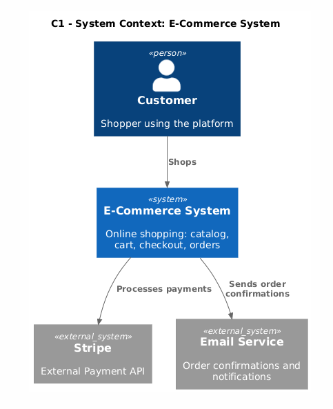
C1. One box: “E-Commerce System.” Around it: the Customer (person), Stripe (external payment API), and the Email Service. Three actors, one system. Any stakeholder can read this in thirty seconds.
C2. The system becomes two containers: “Inventory Service” and “Checkout Service.” Each has its own database. They communicate via events: the Checkout Service publishes an OrderPlaced event; the Inventory Service subscribes and reserves stock. The arrow is labeled: “OrderPlaced event (async).”
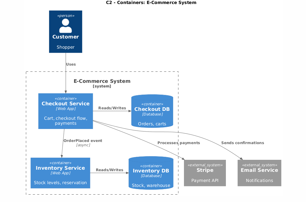
Because we did DDD first, the container names came directly from our workshop vocabulary. The Checkout team and Inventory team point at the same diagram and use the same words.
C3. We could draw one: the Checkout Service has non-trivial internal logic. Tax calculation varies by country and product category. Cart management has its own lifecycle. Those two components have different responsibilities, different change rates, and different ownership. That’s worth a C3.
The Inventory Service? Straightforward CRUD with stock reservation. The code is the documentation. No C3 needed.
C4. Skipped entirely.
The C1 and C2 for this example are exactly what you get from a few lines of PlantUML. Here’s the C1 (System Context):
@startuml ecommerce-c1-context
!include https://raw.githubusercontent.com/plantuml-stdlib/C4-PlantUML/master/C4_Context.puml

Person(customer, "Customer", "Shopper using the platform")
System(ecommerce, "E-Commerce System", "Online shopping: catalog, cart, checkout, orders")
System_Ext(stripe, "Stripe", "External Payment API")
System_Ext(email, "Email Service", "Order confirmations and notifications")

Rel(customer, ecommerce, "Shops")
Rel(ecommerce, stripe, "Processes payments")
Rel(ecommerce, email, "Sends order confirmations")
@enduml
And the C2 (Containers):
@startuml ecommerce-c2-containers
!include https://raw.githubusercontent.com/plantuml-stdlib/C4-PlantUML/master/C4_Container.puml

Person(customer, "Customer", "Shopper")
System_Ext(stripe, "Stripe", "Payment API")
System_Ext(email, "Email Service", "Notifications")

System_Boundary(ecommerce, "E-Commerce System") {
    Container(checkout, "Checkout Service", "Web App", "Cart, checkout flow, payments")
    Container(inventory, "Inventory Service", "Web App", "Stock levels, reservation")
    ContainerDb(checkout_db, "Checkout DB", "Database", "Orders, carts")
    ContainerDb(inventory_db, "Inventory DB", "Database", "Stock, warehouse")
}

Rel(customer, checkout, "Uses")
Rel(checkout, stripe, "Processes payments")
Rel(checkout, email, "Sends confirmations")
Rel(checkout, inventory, "OrderPlaced event", "async")
Rel_R(checkout, checkout_db, "Reads/Writes")
Rel_R(inventory, inventory_db, "Reads/Writes")
@enduml
Drop these into your repo, render them with PlantUML (or the PlantUML web server), and you’ve got version-controlled diagrams that live next to your code.
C4 as AI Context
This one surprised me when I first tried it.
When I start a task in Cursor or prompt Claude for a feature, I paste the relevant C2 diagram at the top of my context. Not as a description of what I want to build; as a description of what already exists. “Here’s our container diagram. Here’s how Checkout communicates with Inventory. Now help me add a returns flow.”
The AI doesn’t have to guess at your architecture. It knows which containers exist, what they’re responsible for, how they communicate, and where the boundaries are. The output is dramatically more aligned with what you actually need, because the model isn’t inventing a structure from scratch.
C4 diagrams are concise enough to fit in a context window and structured enough for a language model to parse. That’s not a coincidence; it’s exactly what makes them good for humans, too.
Where to start
Start with DDD. Run an event-storming session, even an informal one. Find where the same word means different things in different parts of your business; those are your Bounded Context boundaries.
Then draw a C1 and a C2 for your next feature before you write the first line of code. Store them in your repo. Make updating them part of your PR checklist.
Don’t draw a C3 until a meeting breaks down because nobody has the same mental model of a container’s internals. Don’t draw a C4 at all unless you’re required to.
The diagram isn’t the goal. Shared understanding is. C4 and DDD are just the tools that make that understanding durable.
I write about engineering practices and software architecture. Follow me for more.